Electrical integration
Inspect the selected candidate supply, USB audio adapter, matched panel kit, connector map, measurement accessories and remaining qualification gaps.
Open the electronics & wiring editionDESTROYING BOULDERS / ENGINEERING EDITION E01
The housing is only the beginning. Follow the driver, the moving parts, the interfaces and the energy through the next generation of the research.
Research direction: Ashley Kalkowski.
06 October 2026, 19:23 UTC · Digital assemblies and numerical experiments.
NEW / E02 + EL01 + M01
Inspect the selected candidate supply, USB audio adapter, matched panel kit, connector map, measurement accessories and remaining qualification gaps.
Open the electronics & wiring edition112 conditional records quantify return demands and retain the pickup failures. Powered repetition is still an unbuilt mechanism.
Open the reset studyA separate 3D finite-element material comparison adds calculated motion, stress and a video replay, with unresolved convergence exposed.
Open the 3D material labThis E01 page preserves the original assembly/model edition. EL01 supersedes its pending supply/audio selections and uses the complete KAB-PMV3 panel kit; KAB-FC remains a partial alternative, not an additional required purchase. The updated electronics module is external to the acoustic cavity.
01 / A MORE COMPLETE QUESTION
The acoustic route converts electrical input into diaphragm motion. The impact route releases a known moving assembly and accounts for its contact, rebound and capture. Both now have explicit parts and model boundaries.
Two actual driver sizes have separate manufacturer parameters. Rear-chamber volume changes stiffness and the response. Current, back EMF, motion and power are calculated together.
Metal guides, a release pin, a replaceable tip and a secondary capture define one gravity-driven event. Repeated powered timing is a subsequent mechanism requirement.
Kernel geometry checks, exported parts, numerical energy ledgers and failed cases remain inspectable. None of these is a physical fracture test or a promise of a chosen crack.
02 / EXPLORE THE ACTUAL PARTS
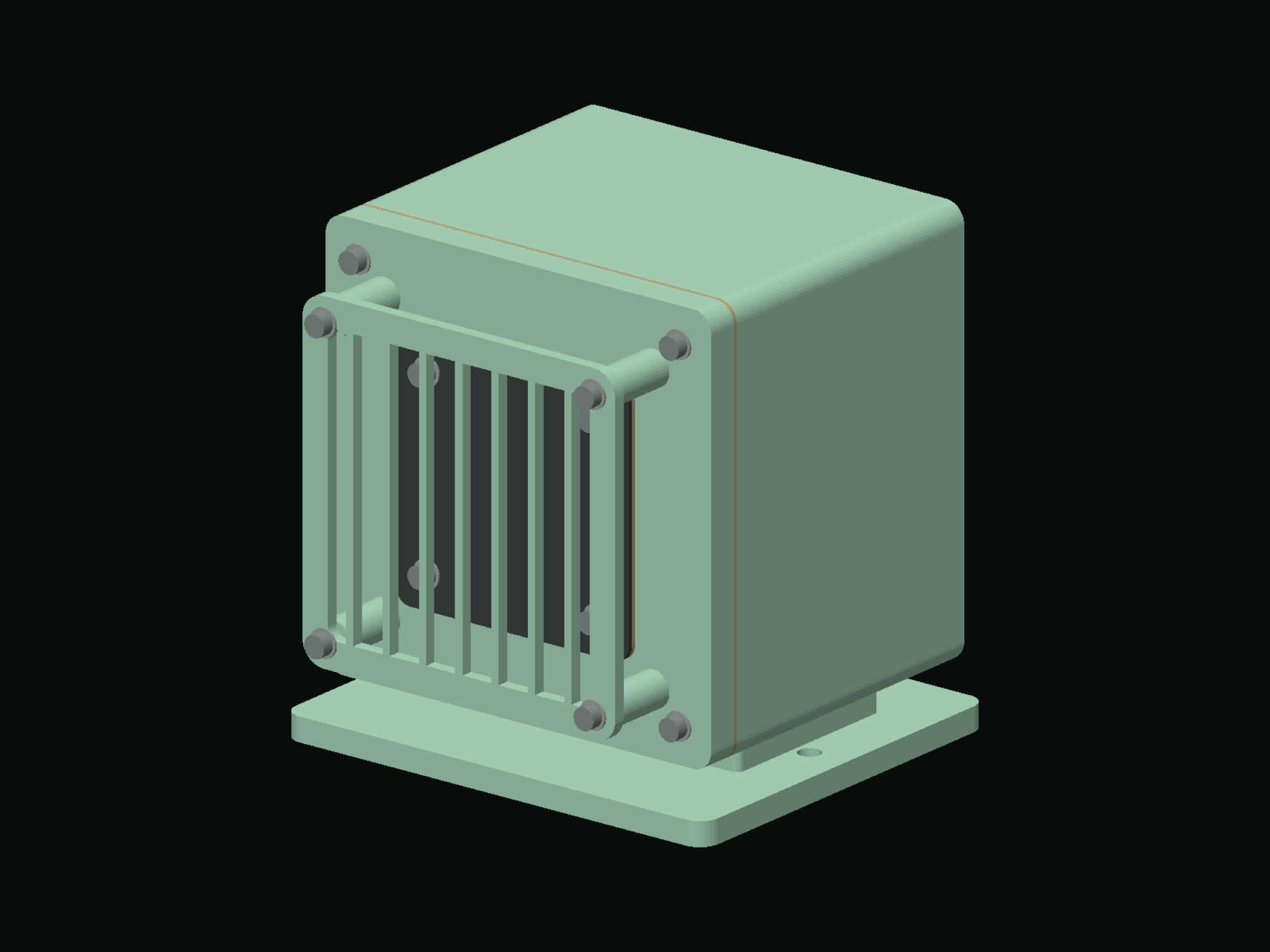
The viewer uses tessellated solids from the CAD export. Select a part, separate the assembly or inspect the section and dimensioned images below.
Loading assembly geometry…
Assembly documents: Acoustic assembly sequence · Acoustic parts list · Impact assembly sequence · Impact parts list
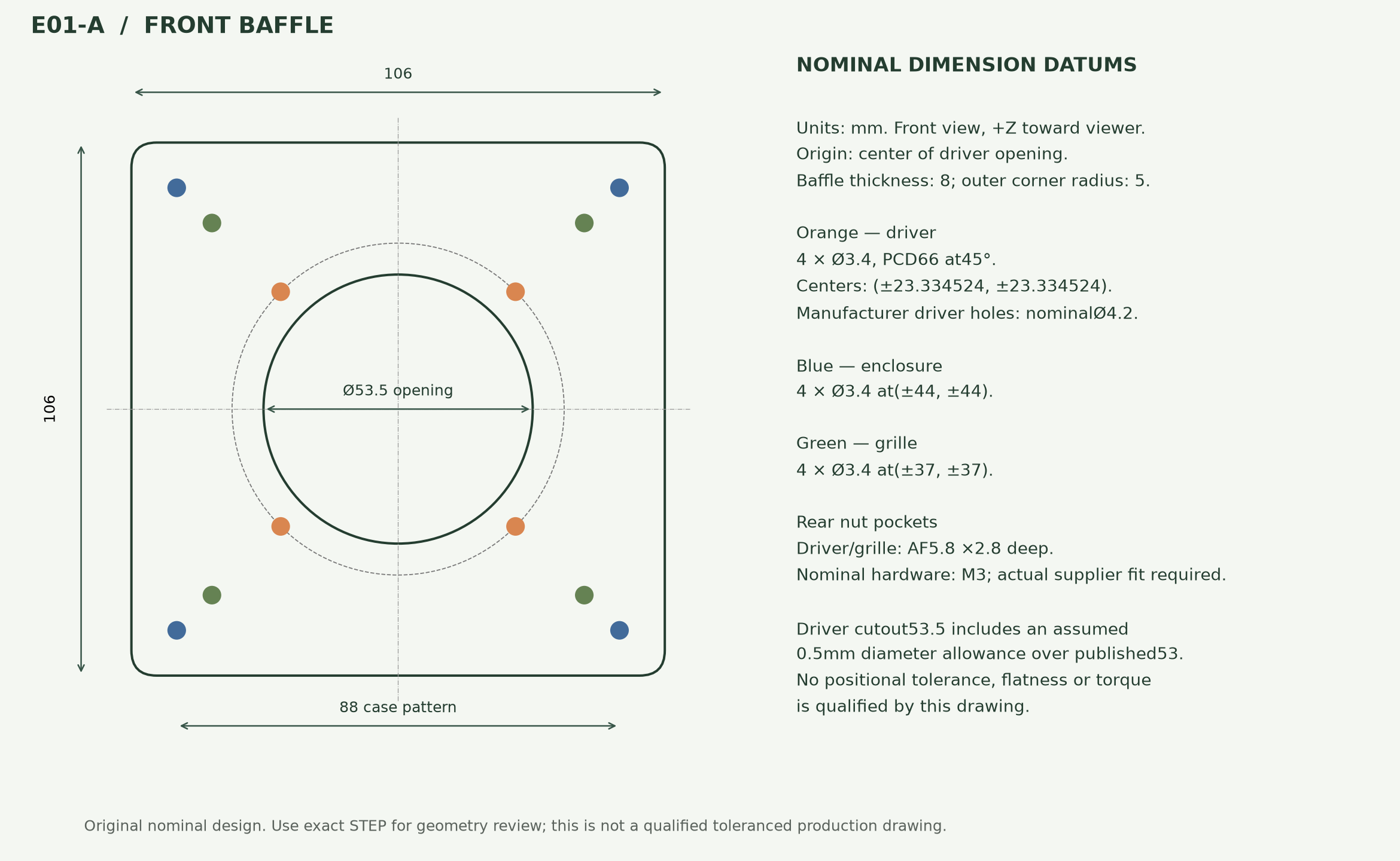
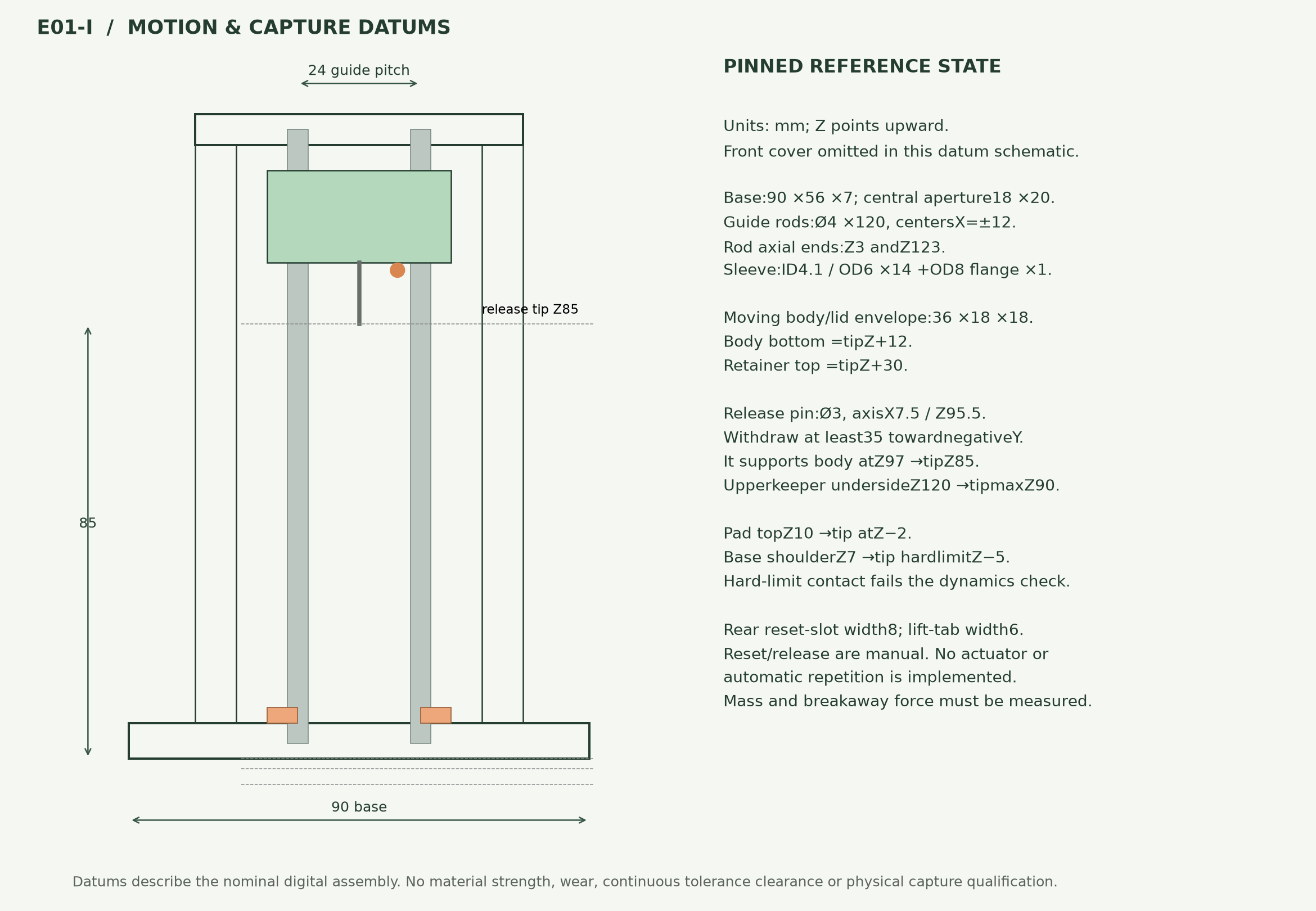
Baffle hole-coordinate sheet · Release and capture datum sheet · Preserved design and export corrections
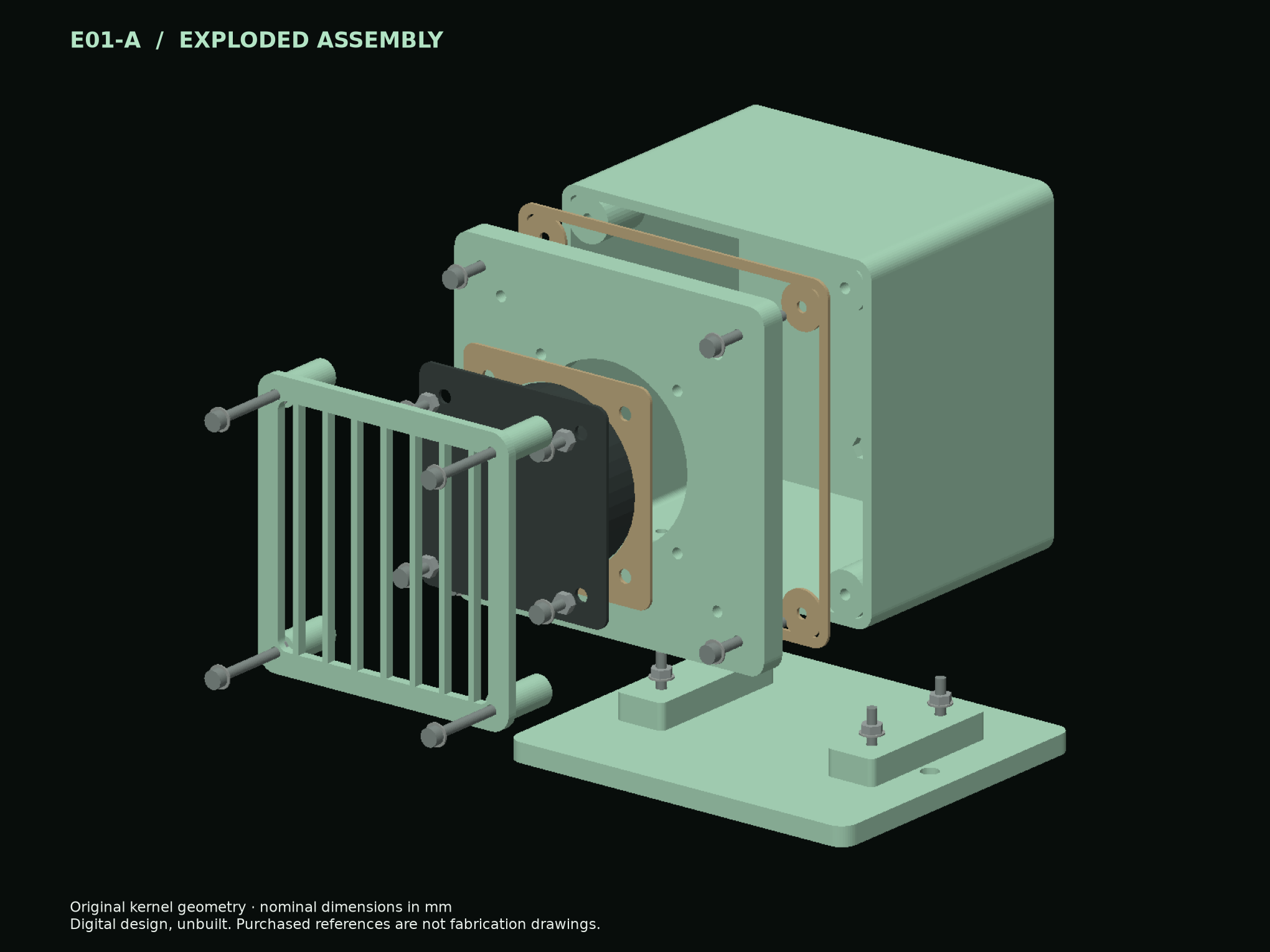
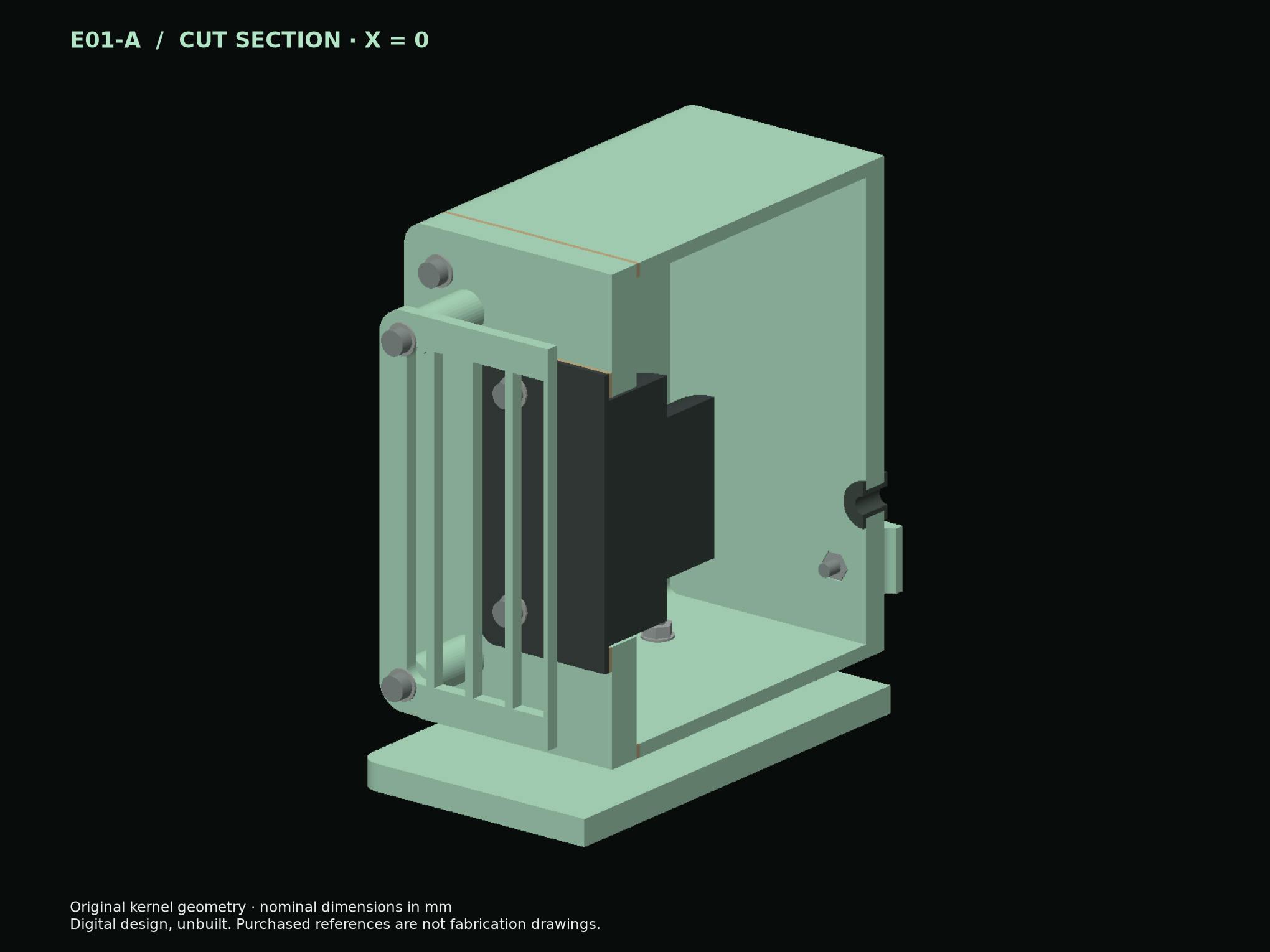
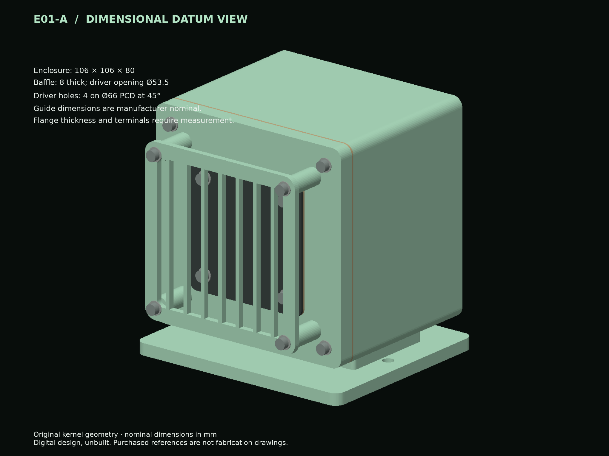
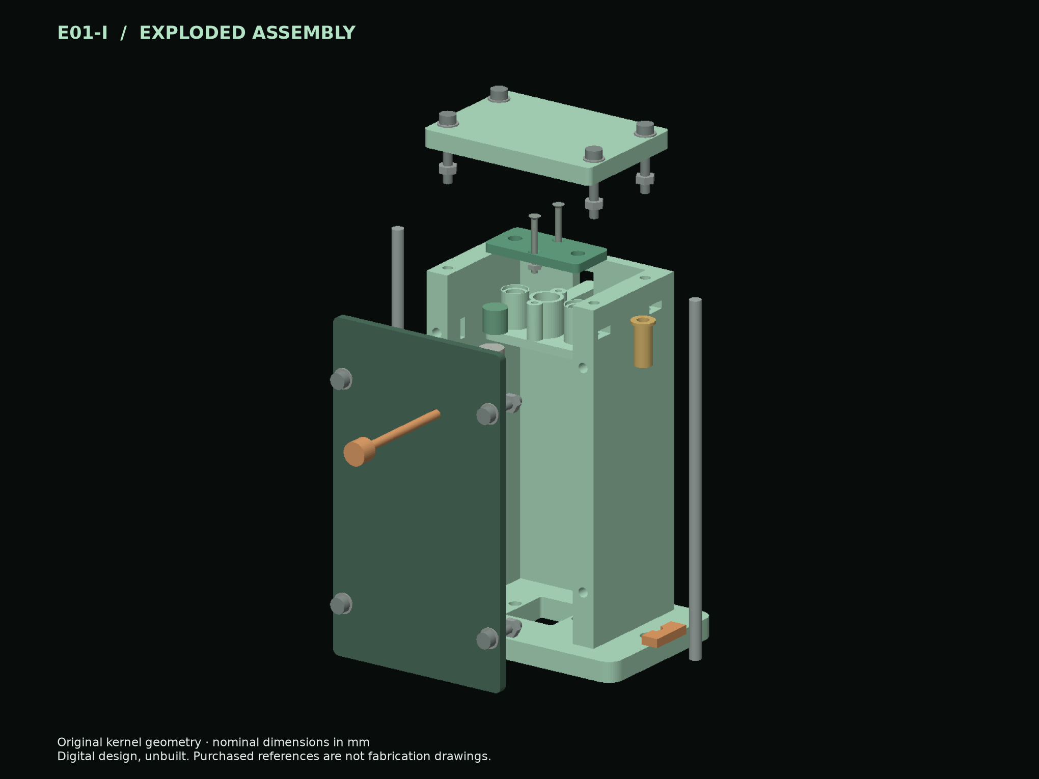
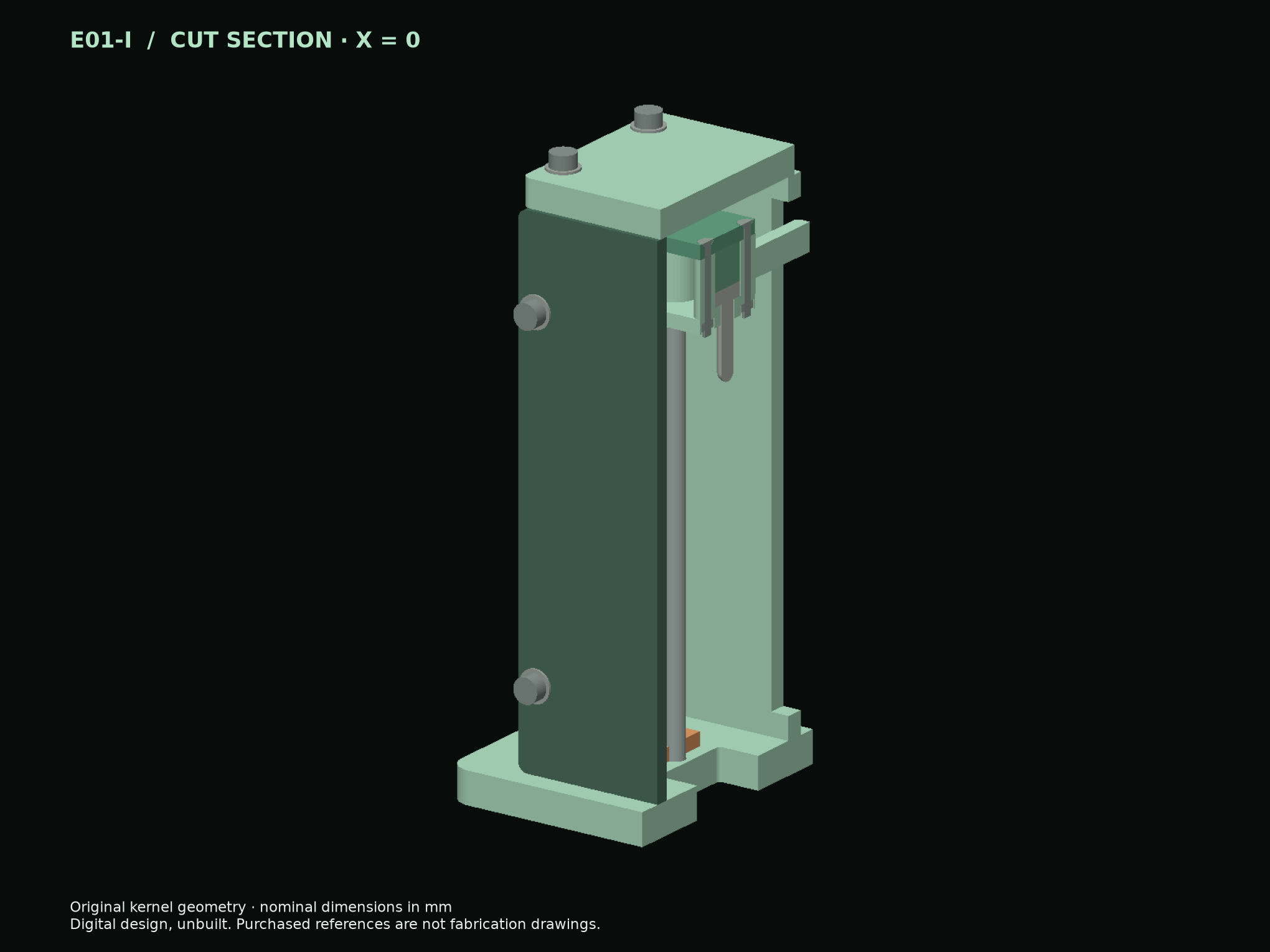
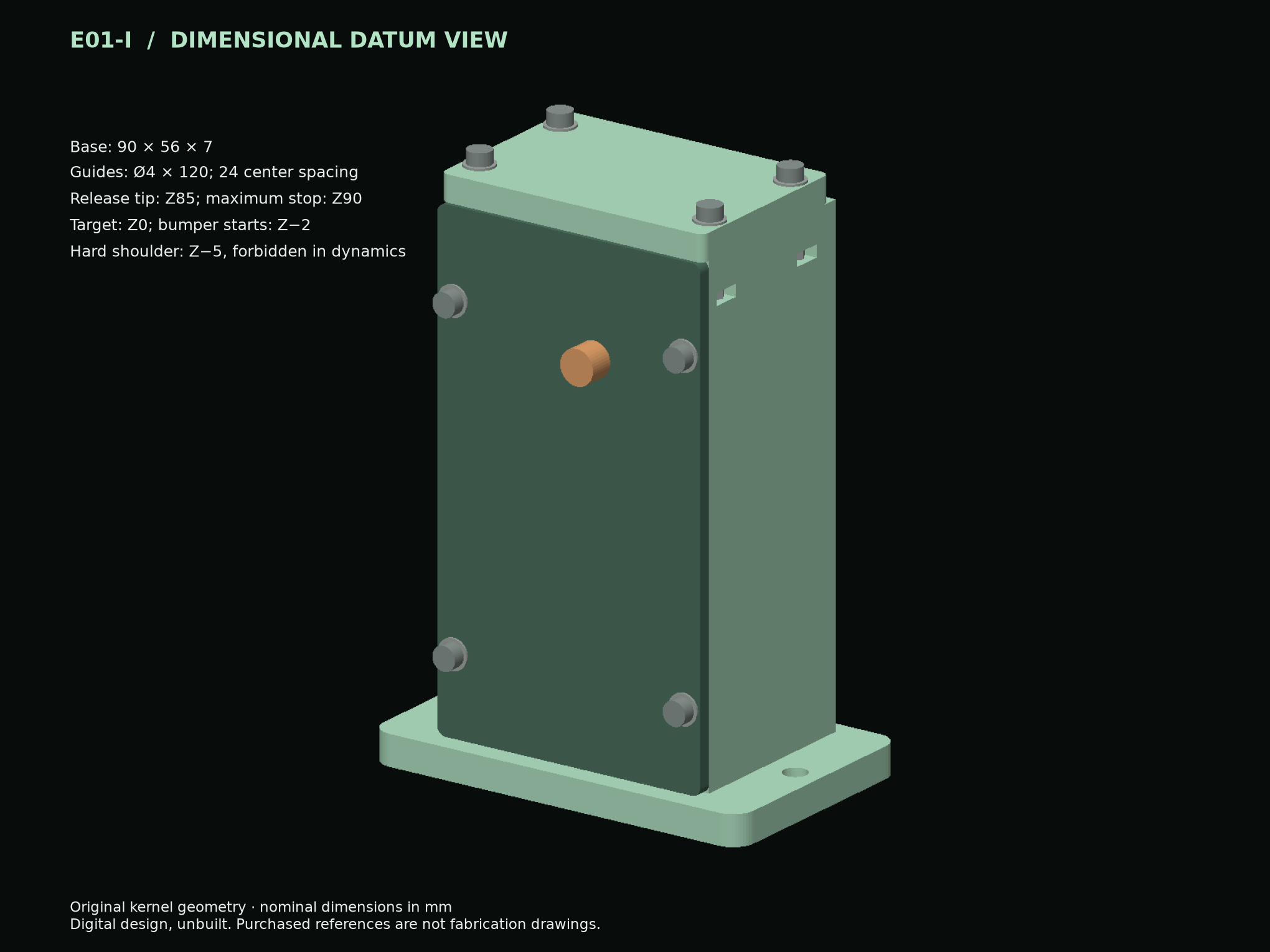
Reference component geometry uses the available catalog datums. Unknown terminal envelopes, part tolerances, material behavior and purchased revisions remain explicit fit gates. A valid CAD solid does not qualify a manufactured part.
03 / THE ACOUSTIC OPERATING MODEL
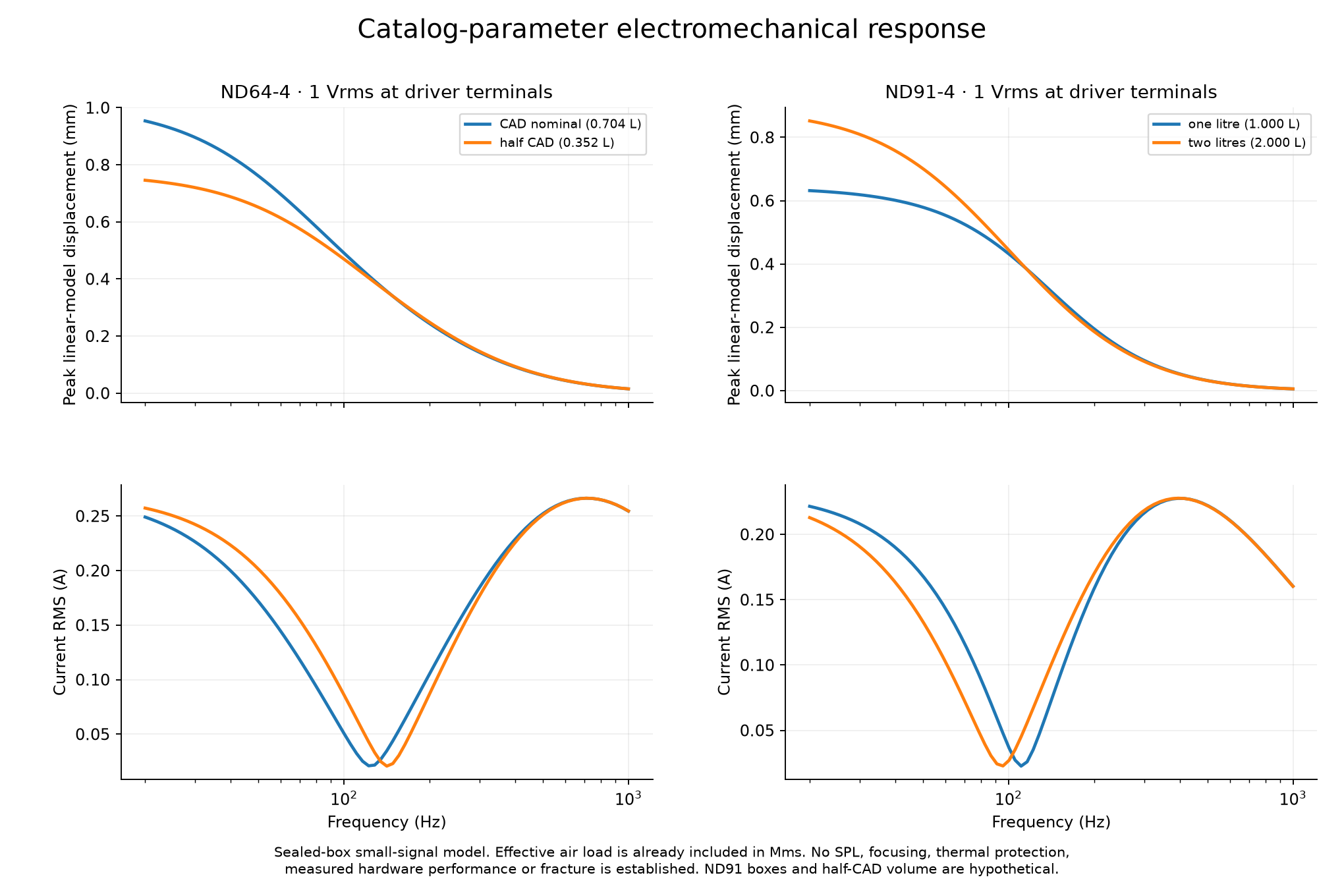
This is a small-signal electrical and mechanical model at the driver terminals. The graph is calculated locally from the documented parameters. It does not generate sound or control equipment.
Input voltage means actual differential RMS voltage at the speaker terminals. Computer volume and digital audio amplitude are not calibrated voltage. The model includes the catalog effective moving mass and aggregate mechanical loss; neither is counted again as a separate radiation term. Box pressure is internal pressure, not sound pressure at a rock.
The reciprocal model couples coil voltage and current to diaphragm velocity through the force factor. Suspension stiffness and ideal sealed-air stiffness act in parallel. In sinusoidal steady state, real electrical input equals copper loss plus the catalog aggregate mechanical loss. The latter does not independently identify radiated acoustic power.
L di/dt = V − Re i − Bl v
M dv/dt = Bl i − Rms v − K x
dx/dt = v
K = 1/Cms + ρ c² Sd²/Vbox
Temperature drift, nonlinear suspension and motor behavior, cone breakup, leaks, enclosure wall compliance, field focusing, specimen coupling and fracture are outside this model. The selected 20–1000 Hz range is a numerical exploration, not a validated band for every omitted effect.
04 / THE IMPACT OPERATING MODEL
D02 found every saved striker still moving at the end of its earlier trace. E01 adds gravity, guide loss, a target and a compliant secondary capture, and retains motion and failures through the end of each new run.
The eight fine-resolution cases retain 1 geometric-boundary failure(s). 2 of 8 meet the prescribed numerical near-rest criterion over the final 50 ms. These are results for the declared hypothetical contact and buffer coefficients, not measured capture ratings.
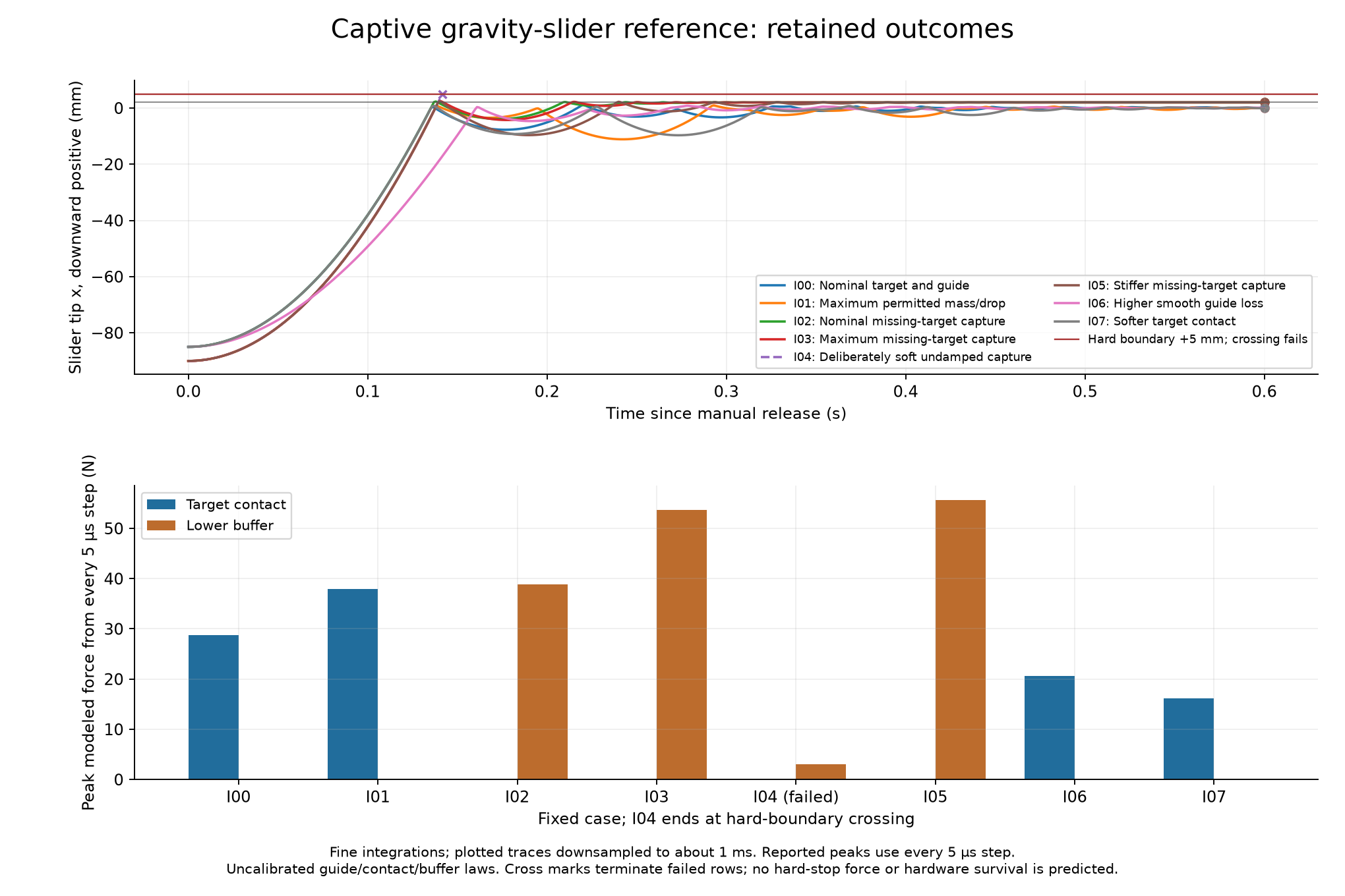
| Case | Target peak | Buffer peak | Retained end | Travel outcome | Motion outcome |
|---|---|---|---|---|---|
| I00 · Nominal target and guide | 28.81 N | 0 N | 0.6 s | Completed window | Rest criterion not met |
| I01 · Maximum permitted mass/drop | 37.88 N | 0 N | 0.6 s | Completed window | Rest criterion not met |
| I02 · Nominal missing-target capture | 0 N | 38.81 N | 0.6 s | Completed window | Near rest in final50ms |
| I03 · Maximum missing-target capture | 0 N | 53.61 N | 0.6 s | Completed window | Near rest in final50ms |
| I04 · Deliberately soft undamped capture | 0 N | 3.004 N | 0.1417 s | Boundary crossed | Rest criterion not met |
| I05 · Stiffer missing-target capture | 0 N | 55.68 N | 0.6 s | Completed window | Rest criterion not met |
| I06 · Higher smooth guide loss | 20.57 N | 0 N | 0.6 s | Completed window | Rest criterion not met |
| I07 · Softer target contact | 16.18 N | 0 N | 0.6 s | Completed window | Rest criterion not met |
The nominal dynamics case assumes a 12 g moving assembly released 85 mm above the target. The CAD material estimate is 12.2047 g; neither value is a measured build mass. Acceptance requires weighing every moving part. The 20 g upper mass and 95 mm maximum release-to-hard-boundary descent correspond to 18.632635 mJ of ideal gravitational work. Guide, contact and capture behavior are assumptions until measured. The manual cartridge establishes one impact; powered reset and controlled repetitive excitation are not implemented here.
05 / THE COMPLETE BENCH CHAIN
The printed head is one part of the system. The amplifier, supply, cables, measurements and specimen fixture belong in the design and the eventual cost.
Printed structures, metal guide and wear surfaces, purchased drivers and fasteners have different jobs. Use the dimensioned parts and fit coupons; do not scale the complete assembly to change driver size.
The component record identifies included harnesses and unresolved terminal fits. A solder-free build is an objective; it is not established until the actual connector sizes and strain relief are checked.
The earlier under $1,000 first-module target remains a constraint. Stock, delivered cost and a complete calibrated bench total have not been verified. These small assemblies do not establish boulder-scale delivery or controlled fracture.
| Subsystem | Candidate / custom part | Current evidence | Manufacturing or calibration gate |
|---|---|---|---|
| Acoustic driver | Dayton ND64-4; ND91-4 is a separate model | Catalog datums, own T/S parameters | Terminal dimensions and actual revision |
| Housing, baffle, grille and gaskets | Original custom CAD | Per-part STEP and custom STL | Process, material, gasket compression and leakage |
| Fasteners and guides | Nominal metal component references | Explicit holes and assembly stack | Thread/grade, engagement, tolerances and moving mass |
| Amplifier and wired harness | Dayton KAB-215v2 with KAB-FC AUX kit | Manufacturer interface documents | Gain, clipping, calibration and exact connectors |
| External supply and PC audio interface | Parts selection pending | Interface requirements documented | Model, complete cost and measurement compatibility |
| Capture buffer and target fixture | Hypothetical compliance in numerical study | Failure cases retained | Measured stiffness, damping, strength and mounting |
Electrical interfaces and characterization sequence · Manufacturer source register
06 / DOWNLOAD & REPRODUCE
Original parametric source, STEP assemblies, individual parts, executable numerical models, frozen inputs and results. Earlier versions and negative outcomes remain available.
Downloads use lossless .tar.xz packaging. Extract each into a fresh folder with Python 3: python -m tarfile -e bundle.tar.xz new-folder. Every extracted member was checked against the original verified source ZIP. Frozen source notes may still name that original ZIP; the commands after extraction and all member bytes are unchanged. The hashes shown here identify the new download containers. Complete bundle contents and file hashes. Historical numerical traces remain individual downloads below.
Parametric CAD source, real STEP exports, custom-part meshes, assembly views, dimensions and component/fit records.
Download · 3.10 MBSHA-256412501d77644cd84ff82aff70aa14066b0ce99d4ff91ecfdf5f494b03de83e52
Frozen inputs, Python models, tests, results, numerical figures and reproduction commands. Full retained NPZ histories are separate.
Download · 1.34 MBSHA-256bb3074fbb9b15d000fa2175b9bf6d1f53fb2be4f5214f378c0be76bd16ed9252
Independent numerical audit, manufacturer parameter records, electrical interfaces and a blank measurement record.
Download · 0.19 MBSHA-25694b0b8de0f3a7aee3aed40cfc6d33ae13489e0fee7e5459989f95dd65292e78c
Inspect the original and corrected-volume histories, their sample meanings, run records and complete public-file hashes.
Open all 52 tracesRun the current models on your PC · CAD regeneration and assembly notes
Original matrix:972 algebraic frequency-response points, 24 acoustic ODE integrations and 16 impact integrations, completed in 137.11 seconds.
Geometry correction:A single-solid check rejected four mounting bosses that only touched the enclosure wall. Joining them changed the nominal air volume from 0.706091 to 0.703978 litres. The separately frozen addendum recomputed 486 affected algebraic points and 12 acoustic integrations in 36.09 seconds. The current 40-integration composite inherits 28 unchanged results; all 52 historical integrations remain available.
Current numerical outcome:Acoustic numerical screens did not all pass; coarse/fine refinement screens passed. One corrected coarse 20 Hz acoustic trace has returned-energy samples as low as −3.10239×10⁻¹² J, failing the frozen −1×10⁻¹² J nonnegative-ledger tolerance. Its finer counterpart passes that gate. The failure remains recorded; accurate amplitude, phase and overall energy balance do not erase it.
Independent sampling finding:A stricter review also detected tiny decreases in sampled cumulative-energy ledgers in 14 historical acoustic traces, up to 1.34×10⁻⁸ J, or 4.42×10⁻⁷ of positive supplied energy. Dense-output interpolation is the likely cause; the original strict audit and frozen results remain intact. Audit agreement means a saved outcome was reproduced, including failures.
Current composite summary · Frozen correction plan · Original matrix · Author tests
Independent review files and geometric acceptance records are included in the downloads. A mathematical check, a valid solid and a physical test answer different questions.
Exact E01 public-file manifest · D02 demands and C02 contact-path correction · Earlier C01 concept family
07 / WHAT WOULD MAKE THIS BETTER?
Measure fit, mass, impedance, terminal voltage/current and motion. Compare measured resonant behavior with the retained predictions without silently changing the original model.
Measure guide friction and buffer behavior, then design a powered reset mechanism with its own timing, thermal and failure analysis. A reserved mounting interface is not a working reset drive.
Identify delivered force or pressure and specimen response before adding calibrated fracture mechanics. The route to a chosen split needs crack-path evidence, not just a resonance peak.
Research direction: Ashley Kalkowski. Computational implementation and review used Codex assistance. Source provenance, established mechanics and third-party dependencies remain attributed. This release does not assert patentability, exclusive rights, manufacturer endorsement or a new blanket reuse licence.