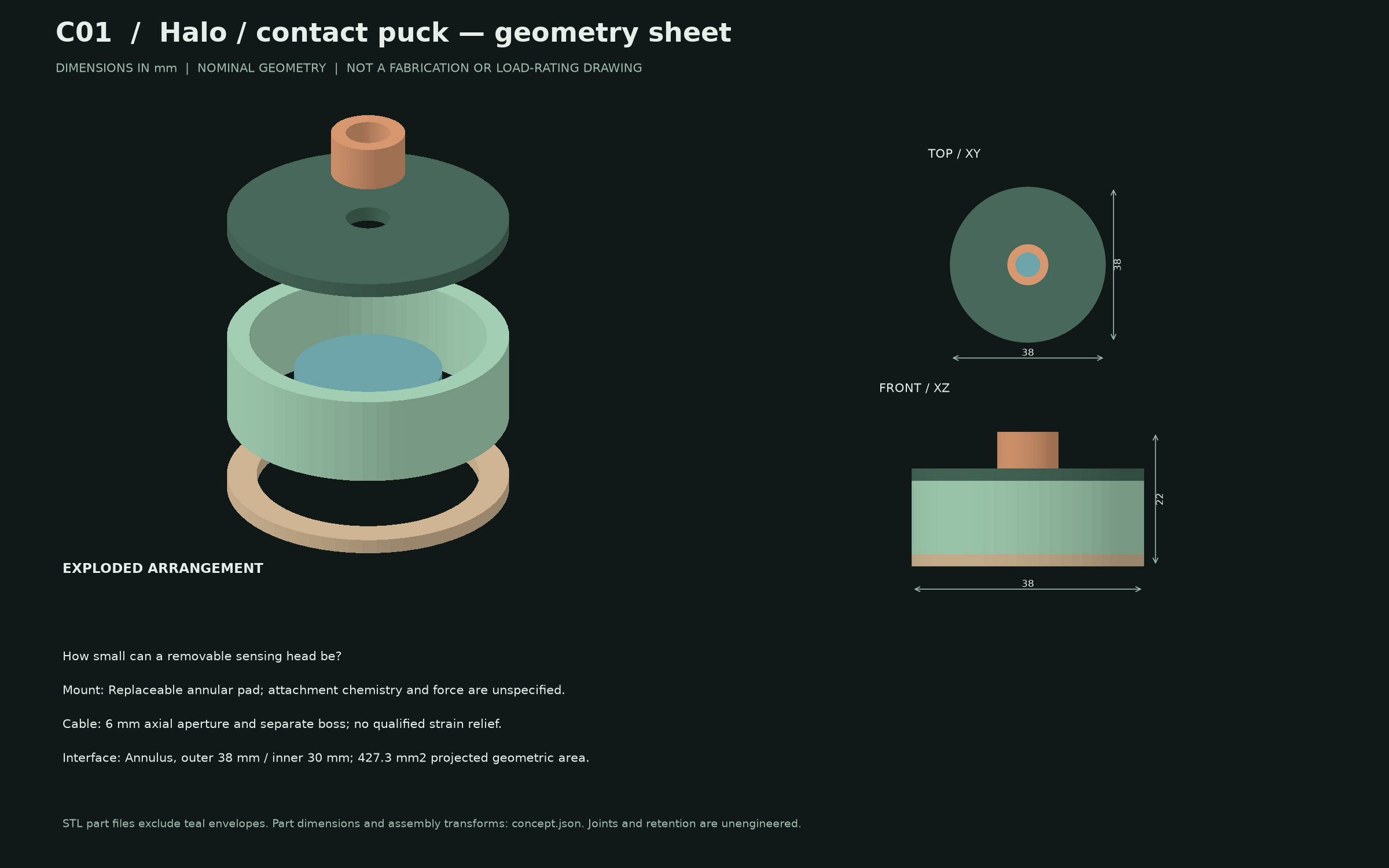
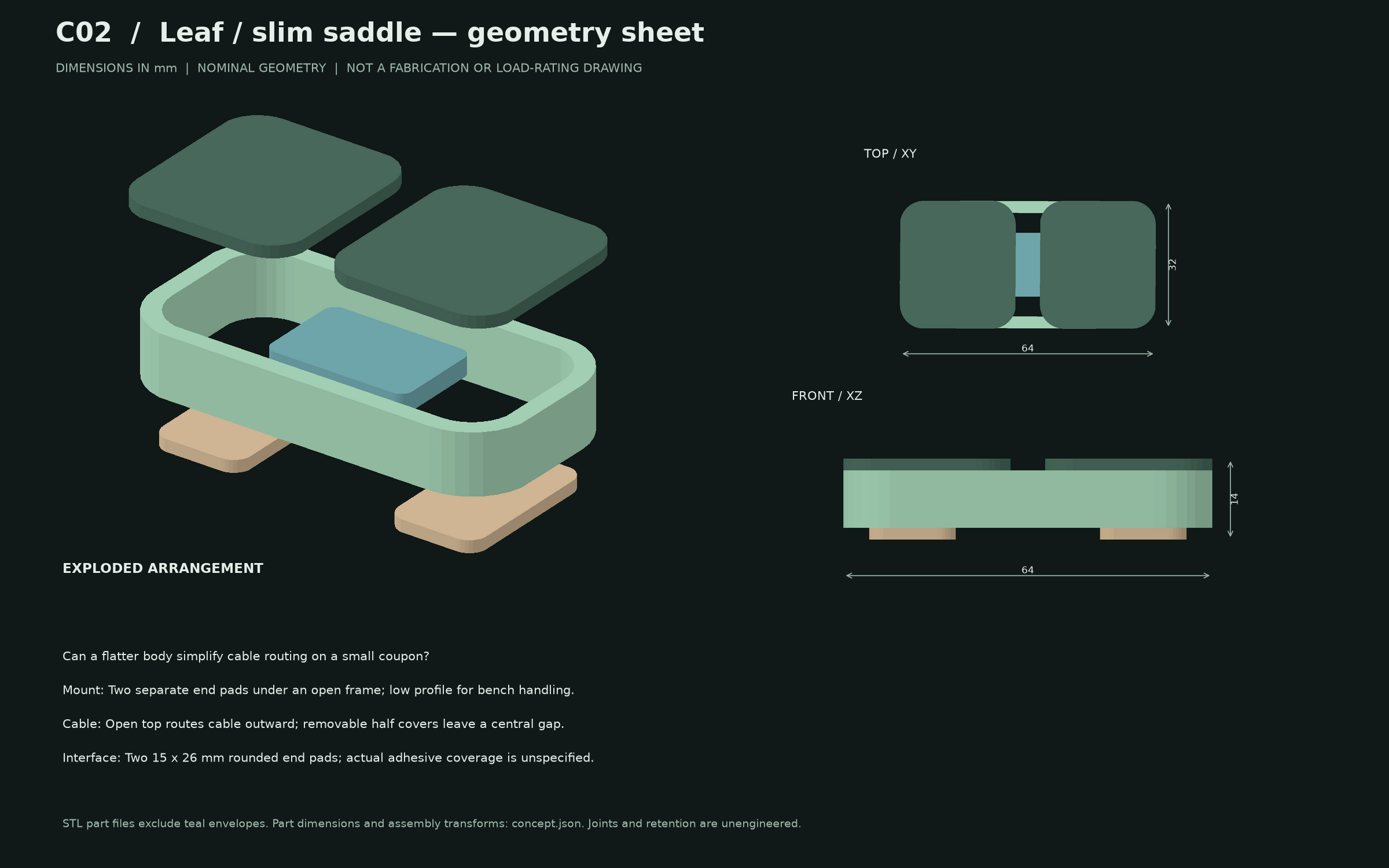
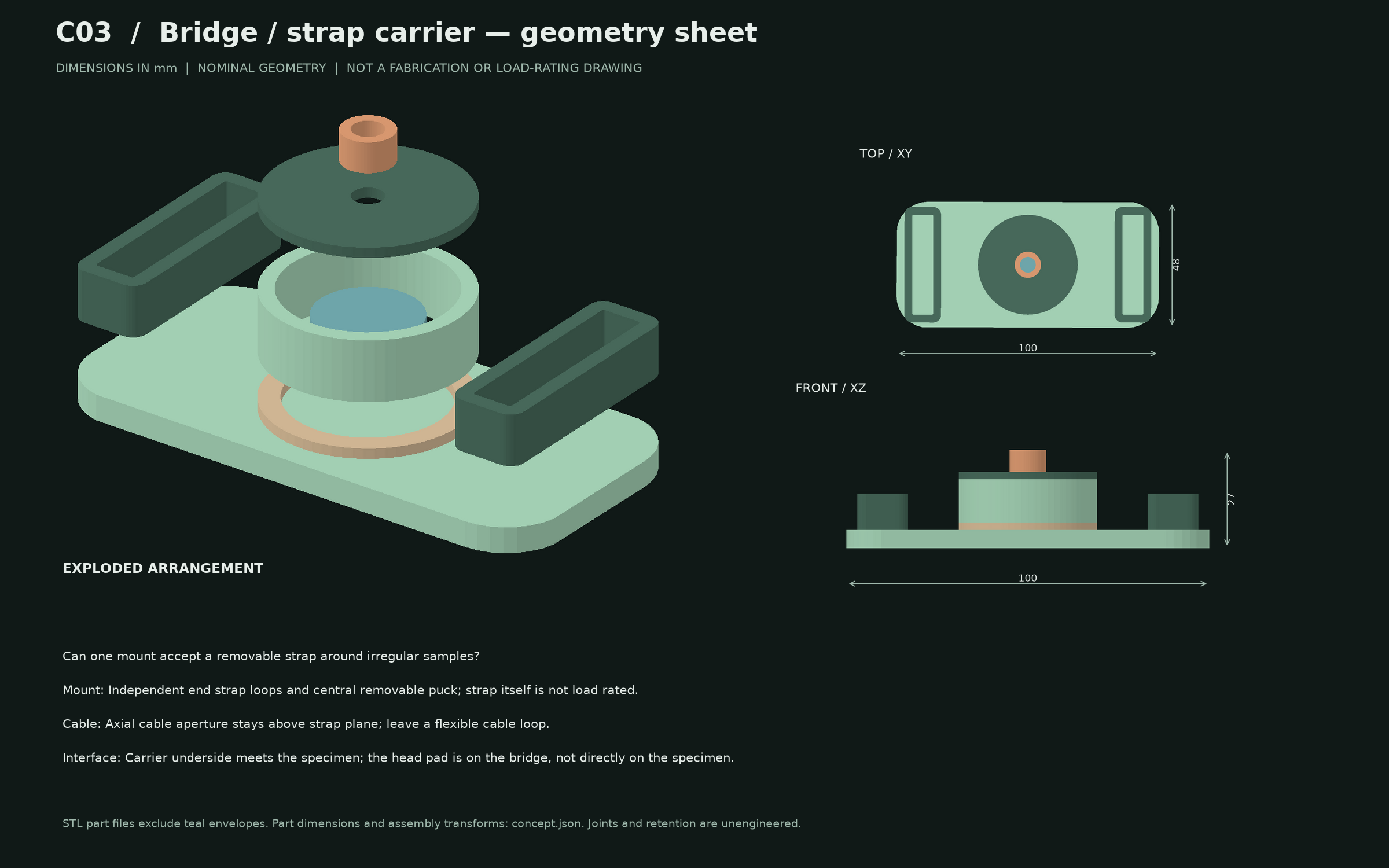
Original CAD geometry / conceptual assembly / not a test photograph
10Original CAD concepts
3 viewsAssembly · exploded · drawing
EditableSource geometry and parameters
Concept stageFit and function still to verify
01 / THE FORM FACTOR STUDY
Different jobs. One design language.
Compact enclosures, deliberate cable exits, mounting options and clear assembly views. Each object addresses a different part of a measurement system; these are not ten proven rock-fracturing devices.
10 conceptsSelect a view on each card. Open an image to inspect it.
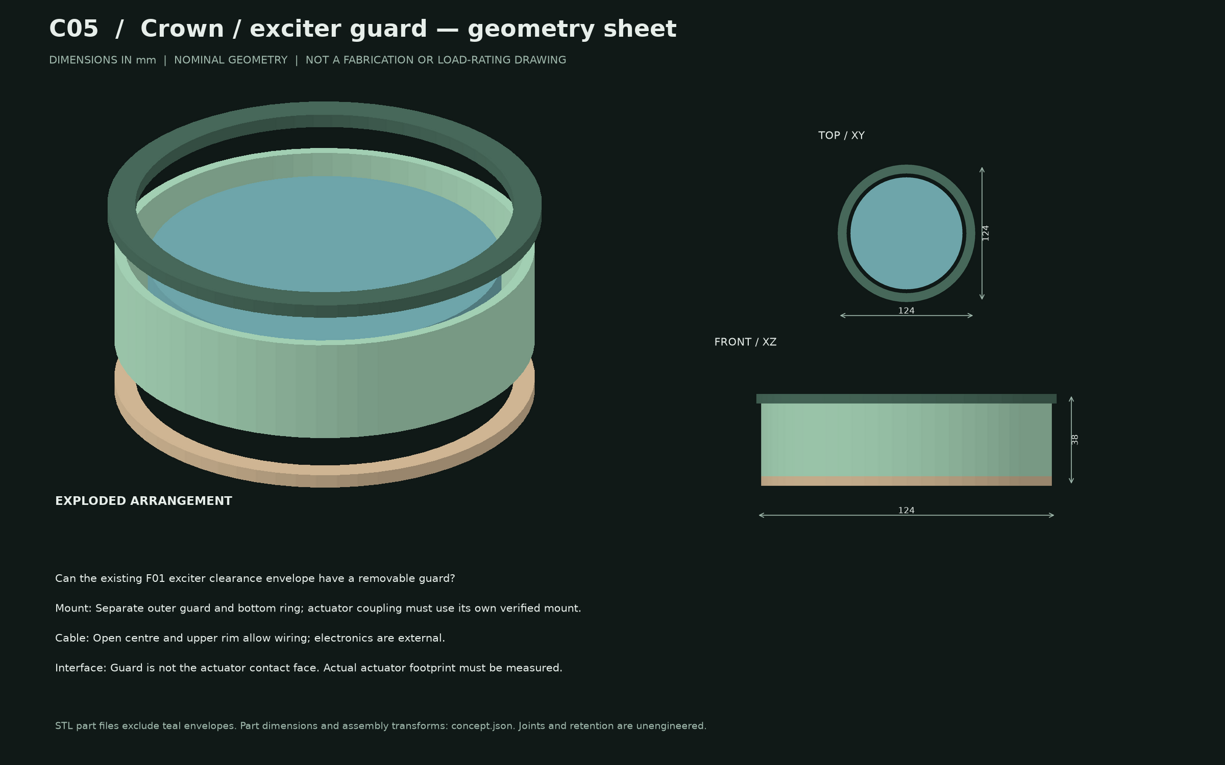
Can the existing F01 exciter clearance envelope have a removable guard?
ASSEMBLY ENVELOPE / 124 × 124 × 38 mm
Interface, mounting and design limits
Contact geometry
Guard is not the actuator contact face. Actual actuator footprint must be measured.
Mount
Separate outer guard and bottom ring; actuator coupling must use its own verified mount.
Cable and handling
Open centre and upper rim allow wiring; electronics are external. Open centre offers visual access; guard rigidity and clearances require real component checks.
Limits
108 mm inner diameter reuses F01 clearance intent only. No force, cooling, sound level or guard strength rating.
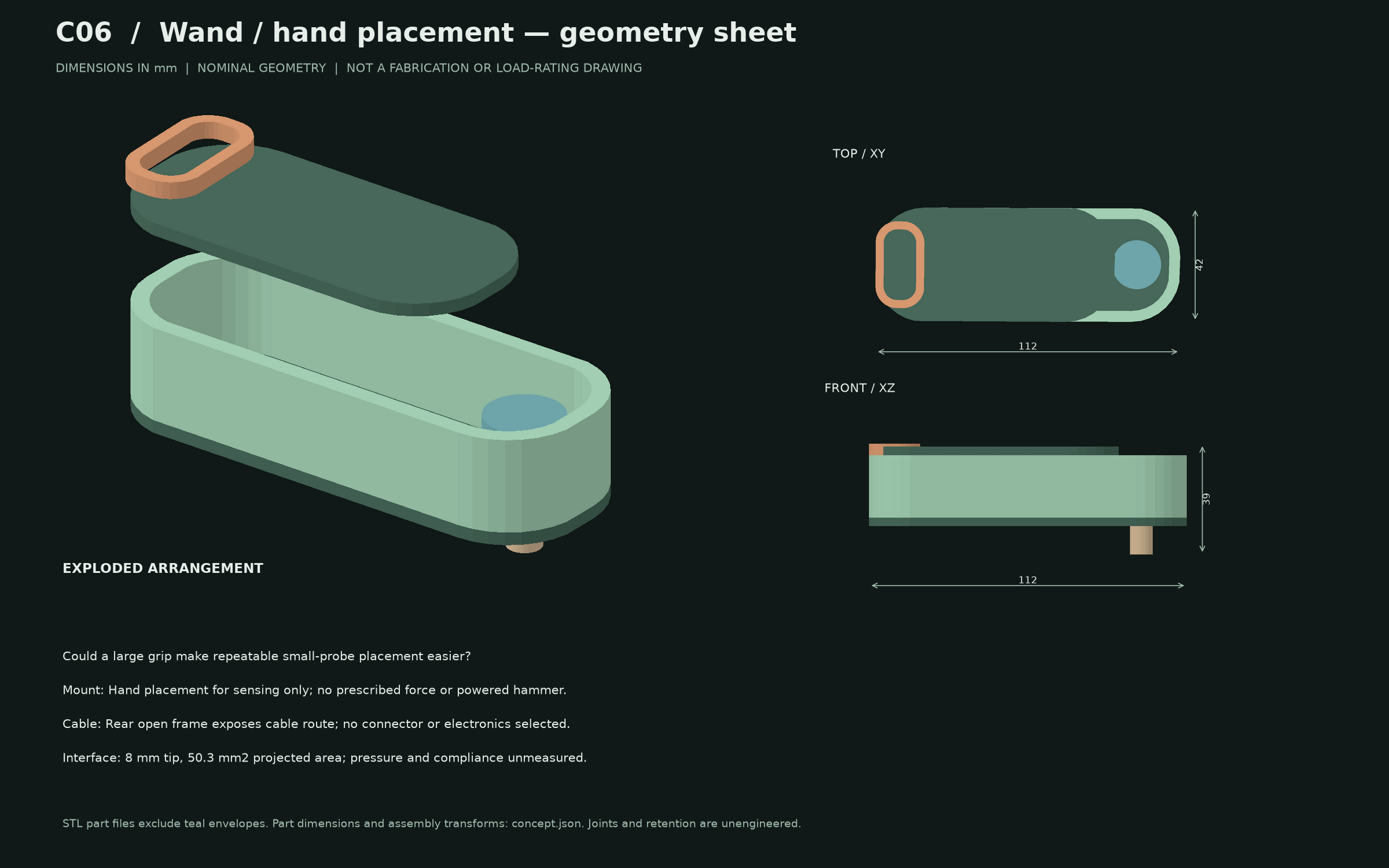
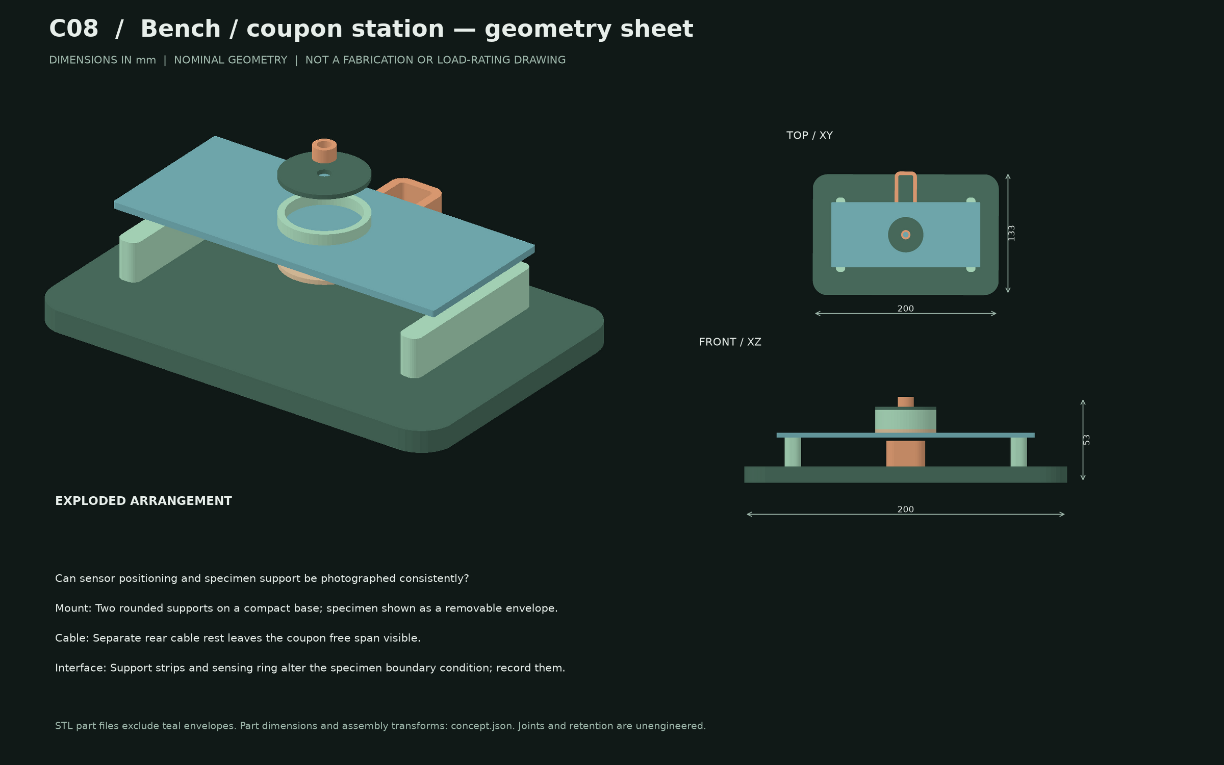
Could a large grip make repeatable small-probe placement easier?
ASSEMBLY ENVELOPE / 112 × 42 × 39 mm
Interface, mounting and design limits
Contact geometry
8 mm tip, 50.3 mm2 projected area; pressure and compliance unmeasured.
Mount
Hand placement for sensing only; no prescribed force or powered hammer.
Cable and handling
Rear open frame exposes cable route; no connector or electronics selected. Long rounded grip supports hand placement; applied force remains an uncontrolled variable.
Limits
Hand force is a confound, not a controlled preload. Grip is a geometric concept; no ergonomic user test.
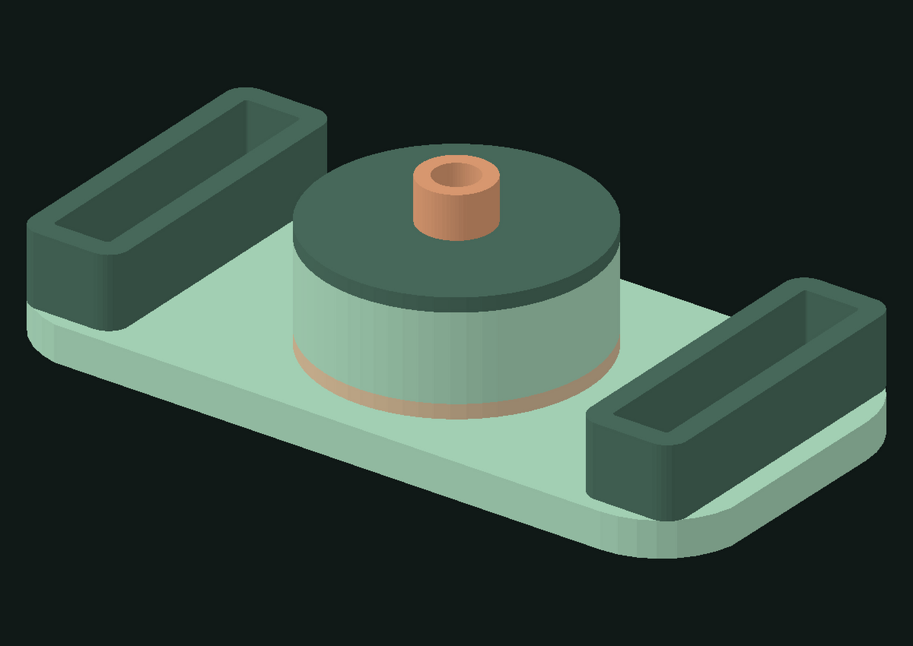
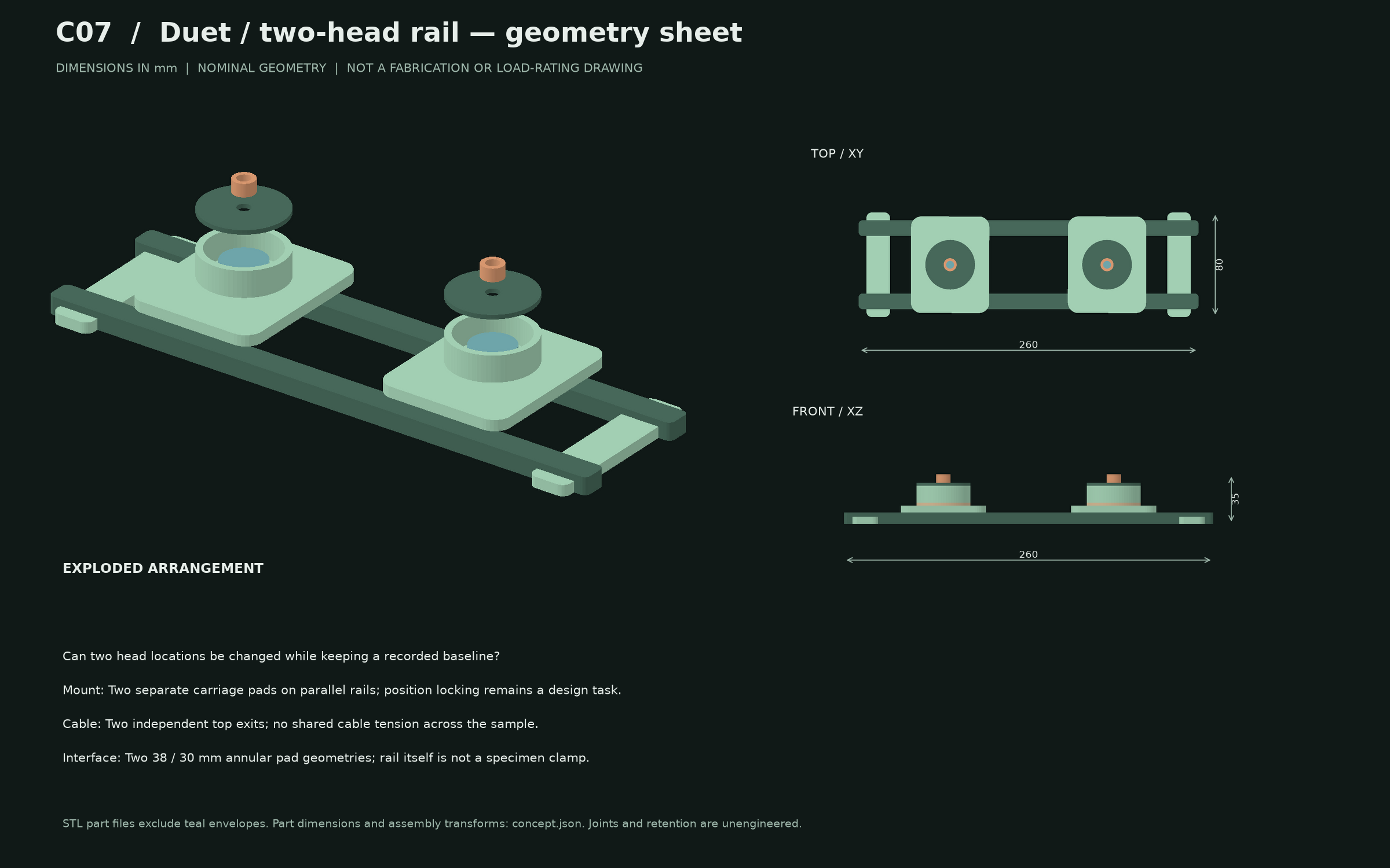
Can two head locations be changed while keeping a recorded baseline?
ASSEMBLY ENVELOPE / 260 × 80 × 35 mm
Interface, mounting and design limits
Contact geometry
Two 38 / 30 mm annular pad geometries; rail itself is not a specimen clamp.
Mount
Two separate carriage pads on parallel rails; position locking remains a design task.
Cable and handling
Two independent top exits; no shared cable tension across the sample. Visible separation of two heads; no working slider lock or one-hand adjustment is specified.
Limits
This is not the simulated 10 g striker system. No travel drive, timing hardware, force sensor or locking hardware is specified.
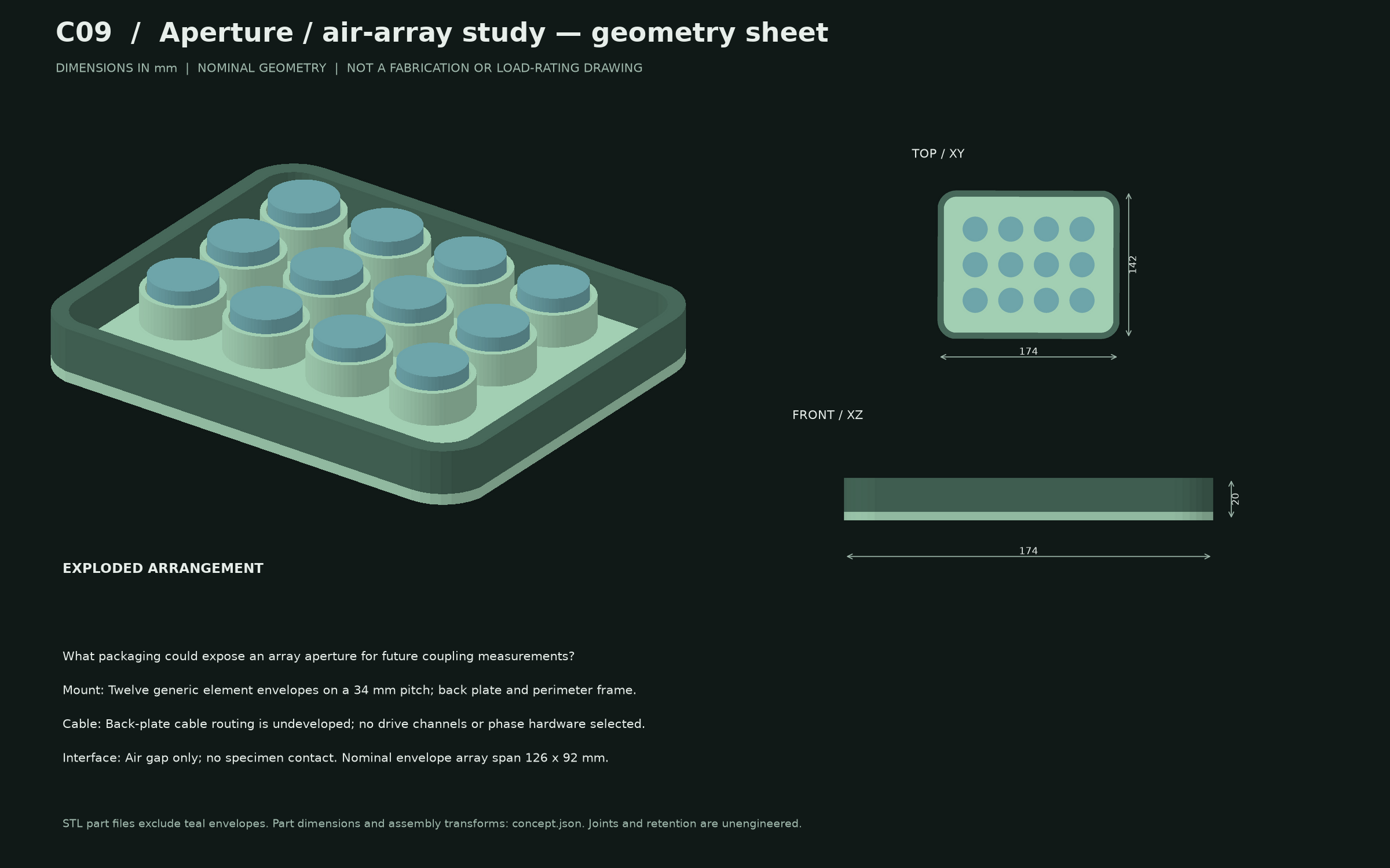
What packaging could expose an array aperture for future coupling measurements?
ASSEMBLY ENVELOPE / 174 × 142 × 20 mm
Interface, mounting and design limits
Contact geometry
Air gap only; no specimen contact. Nominal envelope array span 126 x 92 mm.
Mount
Twelve generic element envelopes on a 34 mm pitch; back plate and perimeter frame.
Cable and handling
Back-plate cable routing is undeveloped; no drive channels or phase hardware selected. Regular element grid is easy to inspect visually; mount, handling and wiring remain undeveloped.
Limits
No acoustic beam, laser analogy, focusing, bandwidth or sound pressure validated. Element dimensions are invented packaging placeholders, not vendor designs. Mechanical collars do not establish phase coherence or electrical feasibility.
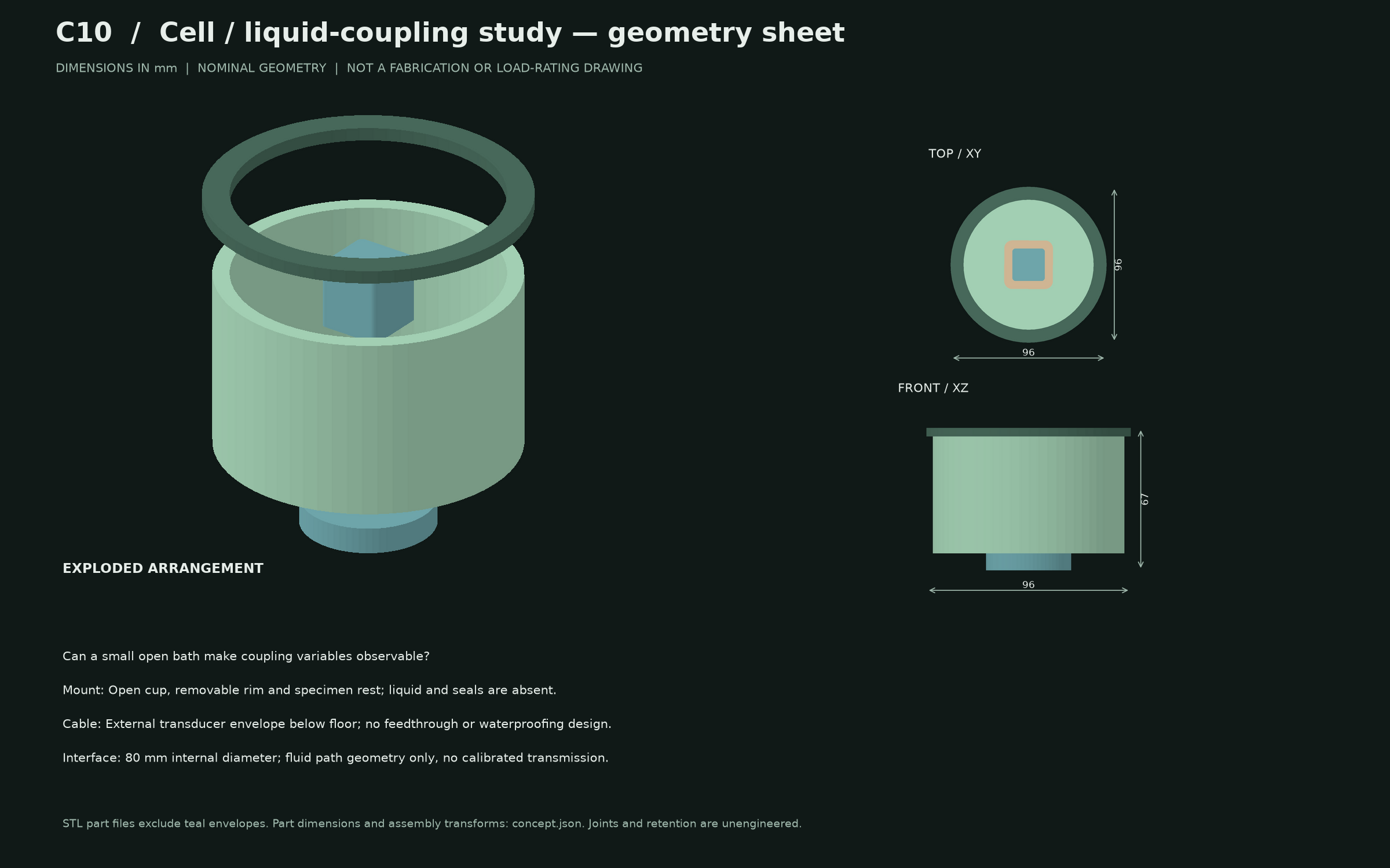
Can a small open bath make coupling variables observable?
ASSEMBLY ENVELOPE / 96 × 96 × 67 mm
Interface, mounting and design limits
Contact geometry
80 mm internal diameter; fluid path geometry only, no calibrated transmission.
Mount
Open cup, removable rim and specimen rest; liquid and seals are absent.
Cable and handling
External transducer envelope below floor; no feedthrough or waterproofing design. Open top allows access to a small sample envelope; leak resistance and electrical separation are unvalidated.
Limits
Not pressure rated, leak tested or approved for powered immersion. No cavitation, lithotripsy, fragment containment or fracture performance represented.
Compact housings can make a measurement setup easier to position. Their outline does not establish delivered force, acoustic focusing, a fracture threshold or a $1,000 working system.
01
Contact first.
A mount must define the actual contact, preload and alignment. A small housing on an irregular rock still needs an interface that can be measured.
02
Make assembly legible.
Exploded views separate the enclosure, internal volume, face and mounting parts. Connector envelopes represent space reservations until actual components are selected.
03
Show the whole system.
Cables, amplifiers, supports and power sources belong in the final footprint and budget. A small probe head is only one part.
04
Test before committing.
Next: fit coupons, selected component clearances, fastening and cable access. Thermal, structural and acoustic performance require their own evidence.
03 / THE PHYSICS, MADE VISIBLE
Follow the energy. Question the picture.
These original diagrams explain mechanisms and model assumptions. Numerical plots elsewhere on the site are linked to their data; these illustrations do not stand in for measured fields.
The complete energy pathFollow the source, driver, interface and specimen. Feedback informs the input; it does not replace the source.Airborne or contact?Different interfaces need different measurements. A rendered head does not establish delivered pressure or force.Several modes, one specimenThree independently normalized analytical cantilever shapes. This is not an irregular-rock simulation.Compression outside, tension insideA disk-loading mechanism that motivates a mechanical question. The line is a reference plane, not a crack result.
The disk-loading reference is discussed in compression and transverse tension. Delivery assumptions and supporting sources are in the D01 delivery study. The cantilever illustration uses the first three analytical Euler–Bernoulli mode shapes, each independently normalized.
04 / OPEN THE GEOMETRY
Inspect the parts.
Download the actual editable geometry, parameter records and rendered views. Use the included scope notes before choosing a part to prototype.
C01 design source & evidence
SCAD sources, geometry-only STL files, dimensioned and exploded views, parameter data, geometry checks and the original diagram generator.
Original, inspectable enclosure and mounting geometry. Dimensions are design inputs. Renders demonstrate the generated shape.
It does not establish manufacturing readiness, a calibrated actuator, a pressure-rated vessel, a certified guard, measured ergonomics or fracture capability. Prototype fit, materials and real component integration remain to be checked.
Publication makes the files inspectable; no new blanket reuse licence or patent-status claim is made by this release.
Release changes and evidence boundary
06 October 2026, 17:55 UTC: added ten CAD concept studies and four explanatory diagrams. The original hand drawing was removed from the current public site at Ashley’s request and preserved in the private development record. Release 04’s illustration was replaced with a labeled schematic; its numerical results and reproducible model archive are unchanged.
These are computational renders of unbuilt concepts. No physical build, specimen fracture or hardware operation took place in this design release. The existing numerical research continues independently.