DESTROYING BOULDERS / D01 / 06 October 2026, 17:27 UTC
How does the energy reach the rock?
A useful fracture system is more than a frequency. Compare the source, the delivery device, its contact with the specimen, and the crack it actually produces.
Research direction and concept: Ashley Kalkowski. This supplement adds analytical screening and a sourced test programme. Physical fracture tests recorded: 0.
01 / SOURCEElectrical, mechanical, hydraulic or thermal input
02 / CONVERTERActuator, impactor, horn, pump or heater
03 / COUPLINGContact, fluid, field or airborne wave
04 / SPECIMENStress, deformation, heat and damage
05 / OUTCOMECrack path, fragments and total energy
The steel-beam question
A waveguide is a delivery device.
A large steel member can carry stress pulses. Its size does not guarantee a controlled fracture through a mountain.
What the calculation can tell us
A one-dimensional elastic rod model relates axial stress, particle velocity, force and traveling-wave power. Increasing cross-sectional area raises the force and power carried at a given stress. The required source power rises with it. This is an ideal axial-wave screen; a real I-beam also has bending, torsion, reflections, joints and contact losses.
With an unspecified unlimited source, “could it break something?” stops being a useful engineering test. The useful question gives a finite source budget, geometry, time, required split and acceptable collateral damage.
What determines the crack
Rock fractures grow in a local stress field and interact with flaws, mineral grains and existing joints. A clean prescribed plane requires evidence about that field and the material's fracture response. A scalar energy total or a resonance peak cannot locate it.
Laboratory granite research has combined controlled loading with acoustic-emission sensing to observe fracture development. That supports measuring the evolving damage, without establishing mountain-scale control. USGS research record
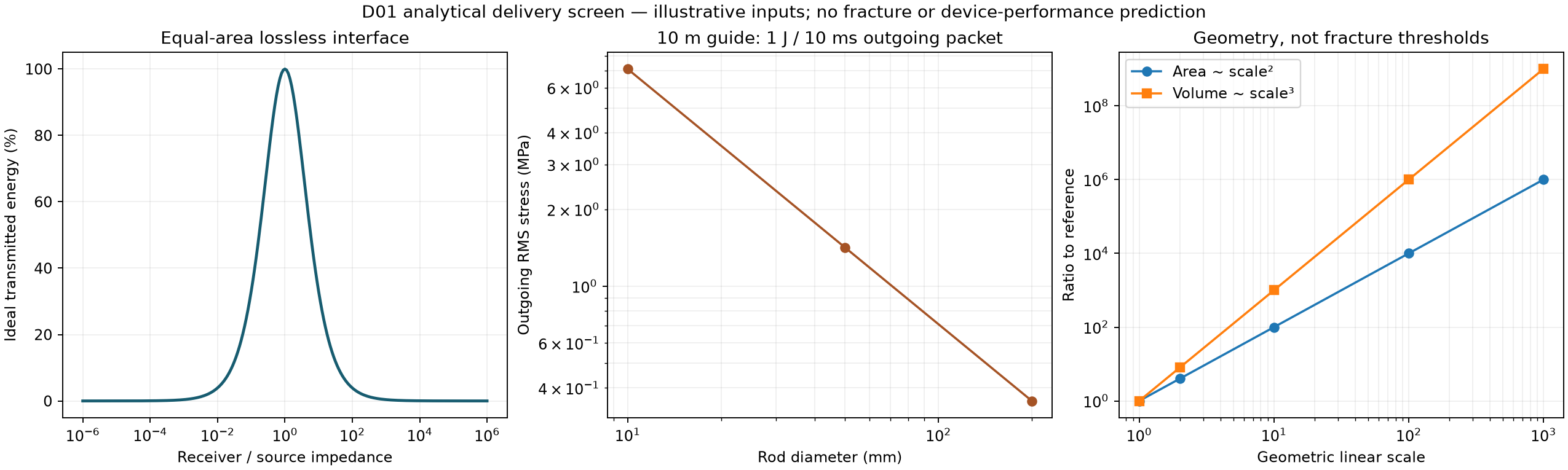
Scaling check: for geometrically similar objects, a proposed split area grows with length squared; mass grows with length cubed. Specific fracture work and the actual participating volume are separate unknowns. The model below reports these geometric factors without inventing a breaking threshold.
A small trigger can sometimes release energy already stored in an unstable rock mass or gravitational configuration. That energy belongs in the accounting; an uncontrolled release is not evidence of a precisely guided split.
The delivery landscape
Different mechanisms. Different tests.
These are research routes with distinct evidence boundaries. The catalogue does not assign unmeasured efficiencies or select a universal winner.
Loading the documented method register…
M01 / Mechanical contact
Instrumented impact and steel waveguide
A striker launches an elastic pulse along a bar or through a contact tip; local tensile/reflected stresses can initiate fracture.
Delivery device
Instrumented striker, elastic bar or replaceable tip, reaction fixture, force/strain sensing.
Evidence supports
Rock impact fracture demonstrated in laboratory specimens; our finite-mass contact model is a beam surrogate only.
Boundary of that evidence
A large steel beam can transport energy but adds inertia and modes; it does not supply energy or force an arbitrary mountain-scale crack.
Testing, variables and primary sources
Measure incident, reflected and transmitted energy, then compare one blow, repeated blows and feedback timing on matched coupons.
Measure striker mass and velocity independently.
Record calibrated force and contact velocity, or appropriately separated bar strain waves.
Check dispersion, reflection timing and dynamic equilibrium before inferring specimen stress.
Measure fragment mass distribution and crack path; include equal-total-input single-impact baseline.
Variables: striker mass, velocity, tip radius, preload, bar diameter and length, pulse width, spacing, contact losses, specimen defects.
Whole-system terms: launcher energy, reset energy, fixture and waveguide mass, lost/reflected energy, tip wear.
Electrical-pulse fragmentation and electrohydraulic shock
Two distinct routes: dielectric breakdown through rock, or an electrical discharge in liquid that generates a pressure wave.
Delivery device
Purpose-built pulsed-power apparatus with electrode/coupling geometry and synchronized electrical, pressure and damage diagnostics.
Evidence supports
Heated granite flakes fractured under electric pulses; separate water-discharge studies damaged mortar and characterized conductivity effects.
Boundary of that evidence
This family is not 'electric resonance.' A demonstrated laboratory discharge is not proof of low total energy, precise crack placement or household assembly.
Testing, variables and primary sources
Reanalyze published energy and damage datasets before any apparatus design.
Retain the electrical pulse waveform and relevant energy boundary.
Measure source energy, discharge energy and target damage separately.
Control conductivity, saturation, electrode condition and initial temperature.
Use CT or ultrasonic measurements plus visible fracture geometry; include sham/thermal controls.
Complete source-linked register (JSON). Numbers quoted from other researchers describe their devices and specimens. They are not performance measurements of this project.
Executable analytical study / D01
Check the transfer before the damage.
Declared scenarios, explicit equations and numerical checks. These algebraic evaluations are separate from the time-integrated beam experiments in the main run catalogue.
Actual generated analytical output. Ideal interface coefficients describe a single encounter with a flat boundary; they are not complete device efficiencies.
An interface changes the energy budget.
For the declared illustrative properties, the single-interface transmitted energy is 0.0122% from air into rock and 35.61% from water into rock. These are ideal plane-wave calculations, not measured end-to-end efficiencies or fracture results.
Airborne delivery, water coupling and perfect solid contact have very different impedance boundaries in this idealization. Matching layers, resonance, repeated reflections, rough contacts, attenuation and mode conversion need their own models and measurements.
Low frequency increases wavelength. It does not automatically make a narrow “sound laser”; a small aperture relative to wavelength is a poor starting point for a tightly directed propagating beam.
6 named interfaces; 241 dimensionless interface points; 9 rod scenarios; 5 geometry scales; 36 wavelength aperture rows. Every declared row is retained in the result file.
What passed, and what remains untested
The retained test report checks interface energy conservation, reciprocity, amplitude-to-energy consistency, finite-input rejection, rod work/energy identities and geometric scaling. Read the exact cases and outcomes in the downloadable evidence.
The screen has no fracture law, crack tracking, three-dimensional rock geometry or calibrated actuator. It cannot determine minimum device size, source power required for a particular boulder, or the probability of a clean split. The assumed medium and steel properties are illustrative inputs, not measurements of Ashley's specimens.
Make the comparison meaningful
Measure the entire job.
Compare methods against the same declared task. A system that makes more dust may be worse at producing one accurate split.
INPUT
Measure supplied energy.
Include the actuator, power electronics, pump, cooling and the cost of repeated probing. Report tool-only and whole-system energy separately.
TRANSFER
Measure the interface.
Synchronize force and velocity for mechanical work. Record calibration, preload, area, supports, motion and coupling changes.
DAMAGE
Observe what changed.
Use before/after geometry, synchronized imaging and calibrated acoustic-emission or ultrasonic records. A sensor pulse alone does not prove a through-crack.
VALIDATION
Predict, then hold out.
Freeze the target plane and stopping criterion. Compare controls, repeats and specimens excluded from calibration, retaining failed and ambiguous trials.
One testable direction combines a mechanically biased crack path with instrumented contact excitation and a damage-based stopping rule. Compare that against the same fixture and energy budget without adaptive timing, as well as against the appropriate conventional method.
This is a proposed experiment. Hydraulic splitting, percussion, ultrasonic drilling and monitoring all have substantial prior art. Combining them is not itself a demonstrated invention or a patentability finding.
Public development
Keep the record reproducible.
The model source, declared inputs, results, tests and generated figure are available below. The existing public evidence remains intact, including unfavorable timing comparisons.
The project is preparing a clearly scoped open-source release. Public source availability and an explicit reuse licence are different steps. No blanket licence or patent licence is asserted for the entire project or third-party work by this update.
The frozen release 07 contact-law experiment remains a separate next numerical task. This D01 supplement does not replace or silently alter that plan.
D01 / Retained evidence and executable source
Inspect it. Run it. Challenge it.
The standalone download contains only the reviewed analytical study, source-linked method register, measurement scorecard and retained results. No hardware commands are included.
D01 changes: adds a delivery-device and testing comparison, a bounded analytical parameter screen, generated figure, executable tests and a reproducible download. Published on 06 October 2026, 17:27 UTC. No physical test images or completed fracture device are claimed.